| Muscle Name | Frame | Growth Proportion (%) | Accumulated Degrees | Moment Arm | PCSAxMomentArm |
|---|---|---|---|---|---|
| temporalis | 0 | 100 | 0 | 2.62562728380496 | 0 |
| temporalis | 1 | 100 | 0.75 | 2.62562728380496 | 0 |
| temporalis | 2 | 101 | 1.5 | 2.63947541985518 | 0 |
| temporalis | 3 | 103 | 2.25 | 2.6541238241366 | 0 |
| temporalis | 4 | 105 | 3 | 2.66946784556233 | 0 |
| temporalis | 5 | 106 | 3.75 | 2.6853978008163 | 0 |
| … | … | … | … | … | … |
Growth Fibers Simulation
1 Introduction
In this tutorial, you will learn how to simulate the growth of muscle fibers in a 3D model using Blender and MUFIS.
We will start assuming that you have a 3D model of an animal already loaded and correctly positioned in Blender and that you have already installed MUFIS. If you haven’t installed MUFIS yet, you can follow the instructions here.
2 Prepare the scene
Before we start simulating the growth of muscle fibers, we need to prepare the scene. For this we need to be sure there are no any other objects in the scene, we only requiere the fixed bone (e.g. the skull) and the moving bone (e.g. the mandible). The first section of the add-on is the Prepare scene section. 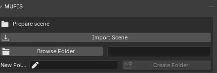
The function of the first button is to import all the elements needed for the simulation. A new collection named Scene Background will be created and include the following elements: - Armature - Background - Camera - Lights - Graph axes and labels - Taxon name (Title of the project)
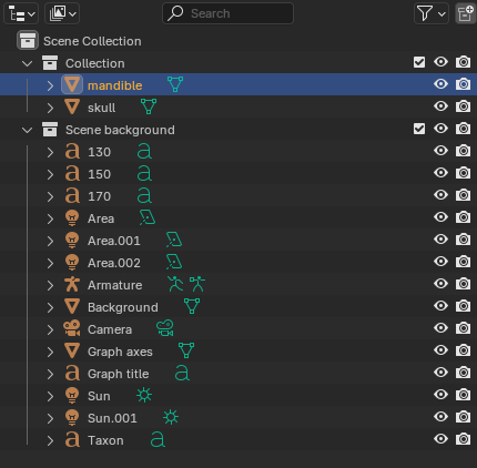
⚠ WARNING: The elements Armature, camera, graph title and Taxon are important for the simulation. If you delete them or rename them, some parts of the simulation may not work correctly. Avoid deleting or renaming them.
As you may notice, the imported elements are probably smaller than your meshes. You will need to scale your models to fit the visualization area. To do this, select the mesh you want to scale and press the S key to scale it. You may also move the mesh by pressing the G key and rotate it by pressing the R key. Press the 0 key on the numpad to see the scene from the camera perspective and adjust the position of the meshes.
In the next section it is necesary to define the path where the results of the simulation will be saved. For this, press the button Browse folder and select the folder where you want to save the results. Next, you will need to define the name of the project. This name will be used to save the results in the selected folder. The name of the project will be used to create a folder with the same name in the selected folder. The name of the project will also be used to create the title of the graph and for the name of the collection where the muscle fibers will be created.
3 Define the articulations
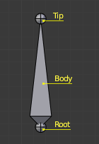
The second section of the add-on is the Define articulations section. In this section the armature is placed on the correct position for simulate the bones movement. The basic element of the armature is the bone. The bone is a 3D object that can be moved, rotated and scaled. It is the basic element for animation in Blender.
The armature is composed by two bones: the fixed bone and the moving bone. The fixed bone is the bone that will not move during the simulation, and the moving bone is the bone that will move during the simulation. The fixed bone is the parent of the moving bone.
 Their position after import them is not important for now, because they will be moved to the correct position now.
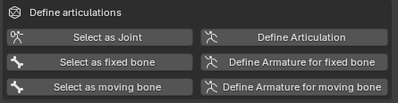
The firs step is to select one of the meshes to be used in the simulation, since both meshes are supposed to be in contact, it is irrelevant which one is selected. After selecting the mesh, press the button Select as Joint, this will turn blender into Edit mode and you have to select the vertex that will be the joint (i.e. the point of contact between the two meshes or rotation center). After selecting the vertex, press the button Define articulation. This will move the middle point of the armature to the selected vertex.
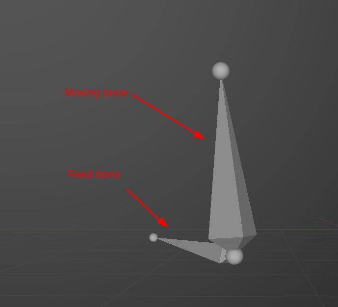
A similar process is necesary to define the fixed and moving bones. First, select the mesh that will be the fixed bone and press the button Select as Fixed Bone. This will turn blender into Edit mode and you have to select the vertex that will be the fixed bone. After selecting the vertex, press the button Define armature for fixed bone. This will move the fixed bone of the armature to the selected vertex. The same process is necesary to define the moving bone. The result should be similar to the following image.
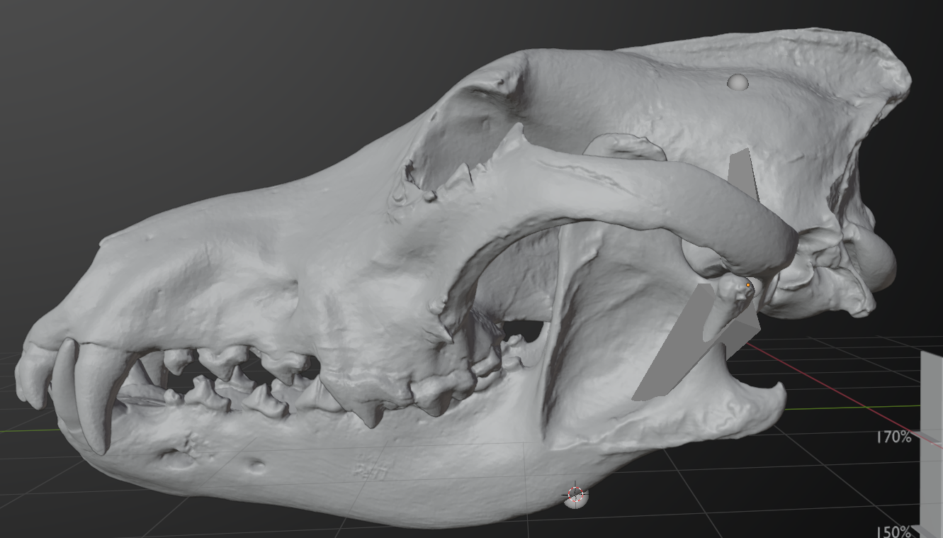
We may test the articulation was correctly defined by moving the moving bone. To do this, select the armature and change blender to Pose mode. You can do this by selecting Pose mode in the upper left corner of the screen. Now you can move the moving bone ggby selecting it and pressing R to rotate it. If the articulation was correctly defined, the moving bone should rotate around the rotation center and the mesh defined as moving bone should move with it.
4 Create the muscle fibers
The next section will be used for creating the muscle fibers. In the first part, you will need to provide a name for the muscle. This name will be used on the graph, the chart and the CSV file where the results will be saved. Be sure to provide a name that is easy to identify and remember. Avoid repeating names when possible. After providing the name, press the button Select Vertex. This will turn Blender into Edit mode and you will need to select the vertex where the muscle fiber will start. After selecting the vertex, press the button Store Origin Muscle to store the coordinates of the vertex. Then, press the button Select Vertex again to select the vertex where the muscle fiber will end. Press the button Store Insertion Muscle to store the coordinates of the vertex. Now you can press the button Add Muscle to create the muscle fiber. However there are some considerations to take into account before creating the muscle fiber.
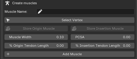
Before creating the muscle fiber, you may input additional parameters.
4.1 Muscle width
It is used to define the width of the cilinder that will represent the muscle fiber. The default value is 0.1. You may change this value to any positive number. The width of the muscle fiber will be the same along the entire length of the muscle fiber. This value does not affect the simulation, it is only used for visualization purposes.
4.2 PCSA
This value is needed only if you are interested in estimating the bite force of the animal. The PCSA is the Physiological Cross-Sectional Area of the muscle fiber. It is the area of the muscle fiber perpendicular to the line of action of the muscle. The PCSA is used to estimate the bite force of the animal. Since we are focus only in sumulating the growth of muscle fibers, and we scaled the meshes to fit the visualization area, the PCSA is not important for this tutorial. You may leave the default value of 0.
4.3 Tendon lengths
In the real world, the muscles are not directly attached to the bones, between these exist another structure called Tendoms, the function of the tendons is to transmit the force generated by the muscle to the bone. If we create a muscle fiber that is directly attached to the bone, it could be unrealistic, since the tendoms possess a different mechanical properties than the muscles. Additionally, tendoms may represent a significant part of the muscle-tendon system length. For this reason, we may be interested in reducing the length of the muscle fiber to simulate the space occupied by the tendons. In MUFIS we may define a percentage of the muscle fiber length that will be used to simulate the tendons on both ends of the muscle fiber. A value of 10% on the origin tendon length means that the 10% of the muscle fiber length will be reduced on the origin side of the muscle fiber. The same applies for the insertion tendon length. The default value is 0, which means that the muscle fiber will be attached directly to the bone. You may change this value to any positive number.

Image source: Wikimedia Commons
We may create as many muscle fibers as we want. The only limitation is that the visualization may be compromised if we create too many muscle fibers. It is highly recommended to check anatomical references to create the muscle fibers in the correct origin and insertion points. Also it is importan to decide the subdivisions we will use for each muscle (e.g. the masseter muscle may be divided in superficial and deep portions). In case you want to delete a muscle fiber, you may select the muscle fiber in the scene and press X to delete it or you may delete it from the scene collection. Also is possible to press Ctrl + Z to undo the creation of the muscle fiber. This is helpful for example if you want to change the width, the PCSA or the tendon lengths of the muscle fiber. Since the coordintates of the origin and insetion points are stored, you don’t need to select them again.
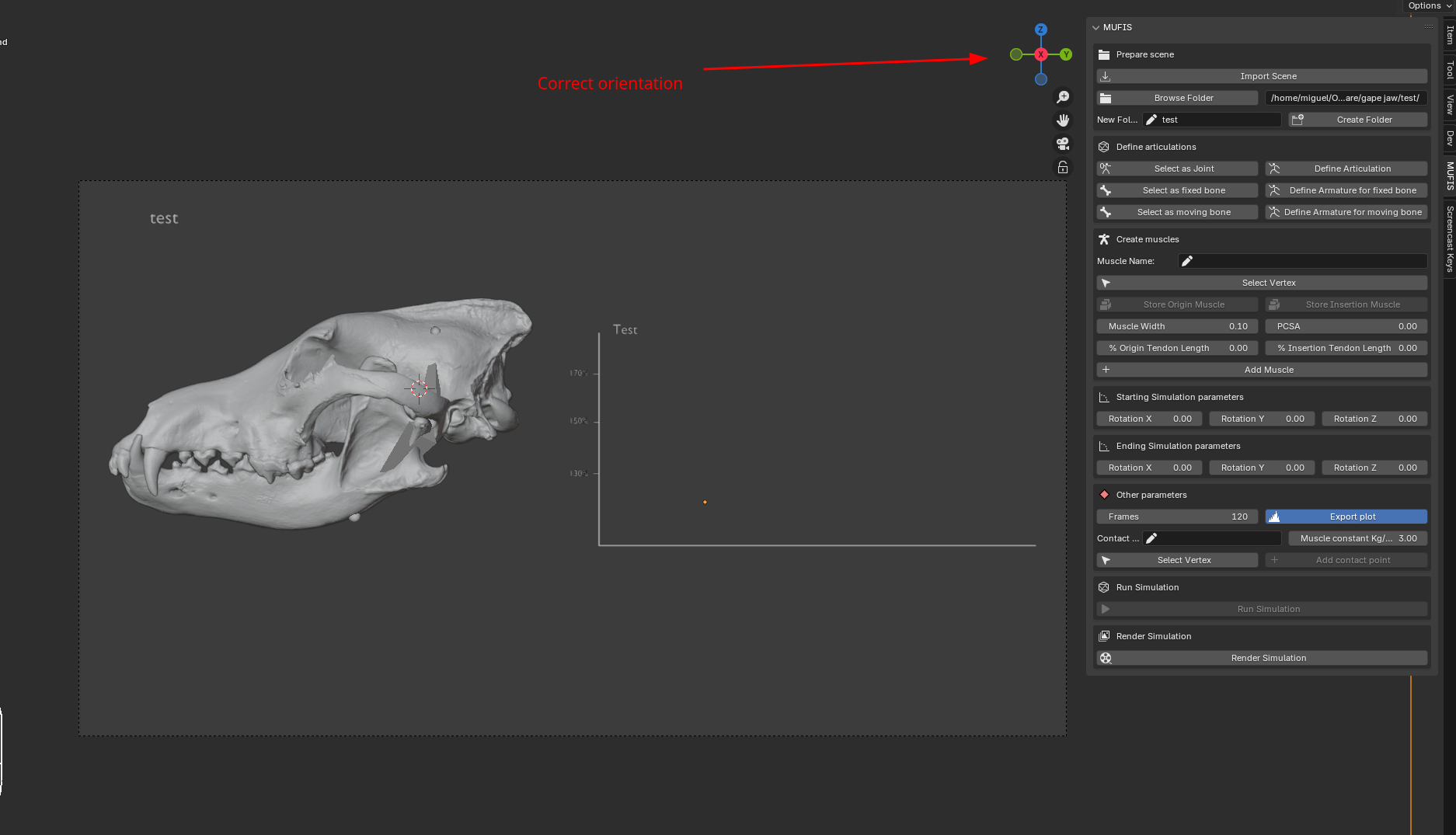
5 Simulation parameters
The simulation parameters are used to define the axis and degree of rotation of the simulation. By default, the X axe is used in the calculation. This means that your meshes should be oriented in such a way that the X axe is perpendicular to the line of action of the muscle (e.g. a skull and jaw on lateral view). This can be seen by pressing the 0 key in the numpad to see the scene from the camera perspective.
It is known that the maximum force that a muscle can generate is produced when the muscle is at its optimal length. This is because the muscle fibers are aligned in such a way that the maximum number of cross-bridges can be formed. If the muscle is stretched or contracted, the number of cross-bridges that can be formed is reduced, and the force that the muscle can generate is also reduced. This position may vary depending on the muscle. According to Lautenschlager (2015), for theropod dinosaurs, there is no information about the specific angle at which the muscles are at their optimal length. For this reason, he tested the simulation at different anglles. For our example, we will set a value of 5 degrees (Cero degrees means that the animal has its mouth fully closed). This mean that the jaw will be rotated 5 degrees from the current position and at this point the simulation will start. As ending parameters, we will set a value of 55 degrees. This means that the jaw will be rotated 55 degrees on the X axe from the current position and at this point the simulation will end. We will keep the supplementary axes Y and Z at 0 degrees. This means that the jaw will not be rotated on these axes.
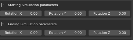
Note: the rotation of the x axe is positive in the counterclockwise direction. This means that the jaw will be rotated in the counterclockwise direction.
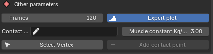
6 Adittional parameters
It is possible to provide additional parameters for the simulation. The following parameters are available:
- Frames: The number of frames that will be used in the simulation. The default value is 120. This means that the simulation will be divided in 120 frames during the animation. We recommend to keep this value at 120.
- Export plots: If this option is checked, the plots generated during the simulation will be saved as interactive HTML files if the extension version is used and as PNG files if the add-on version is used. The HTML files can be embedded in web pages or exported to other formats like PNG or SVG. The default value is checked.
- Contact Points: This option is used to select the contact points where the biteforce will be estimated (see Bite Force Estimation tutorial). For this tutorial, we will not use those options.
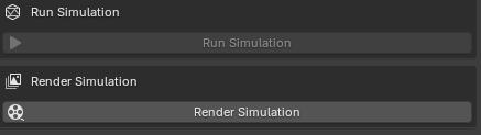
7 Run the simulation
After generating all the muscles and the rotation parameters, you can press the button Run Simulation to start the simulation. The simulation will start rotating the jaw from the current position to the starting position (5 degrees in this example). The length of the fibers will be calculated considering this position as the optimal length of the muscle fibers. The simulation will end when the jaw is rotated to the ending position (55 degrees in this example). The length of the muscle fibers will be calculated at each frame of the simulation. The results will be saved in a CSV file in the selected folder. The results will include the name of the muscle, the frame number, the length of the muscle at that frame, the moment arm (the distance between the temporomandibular joint and the line of action of the muscle).
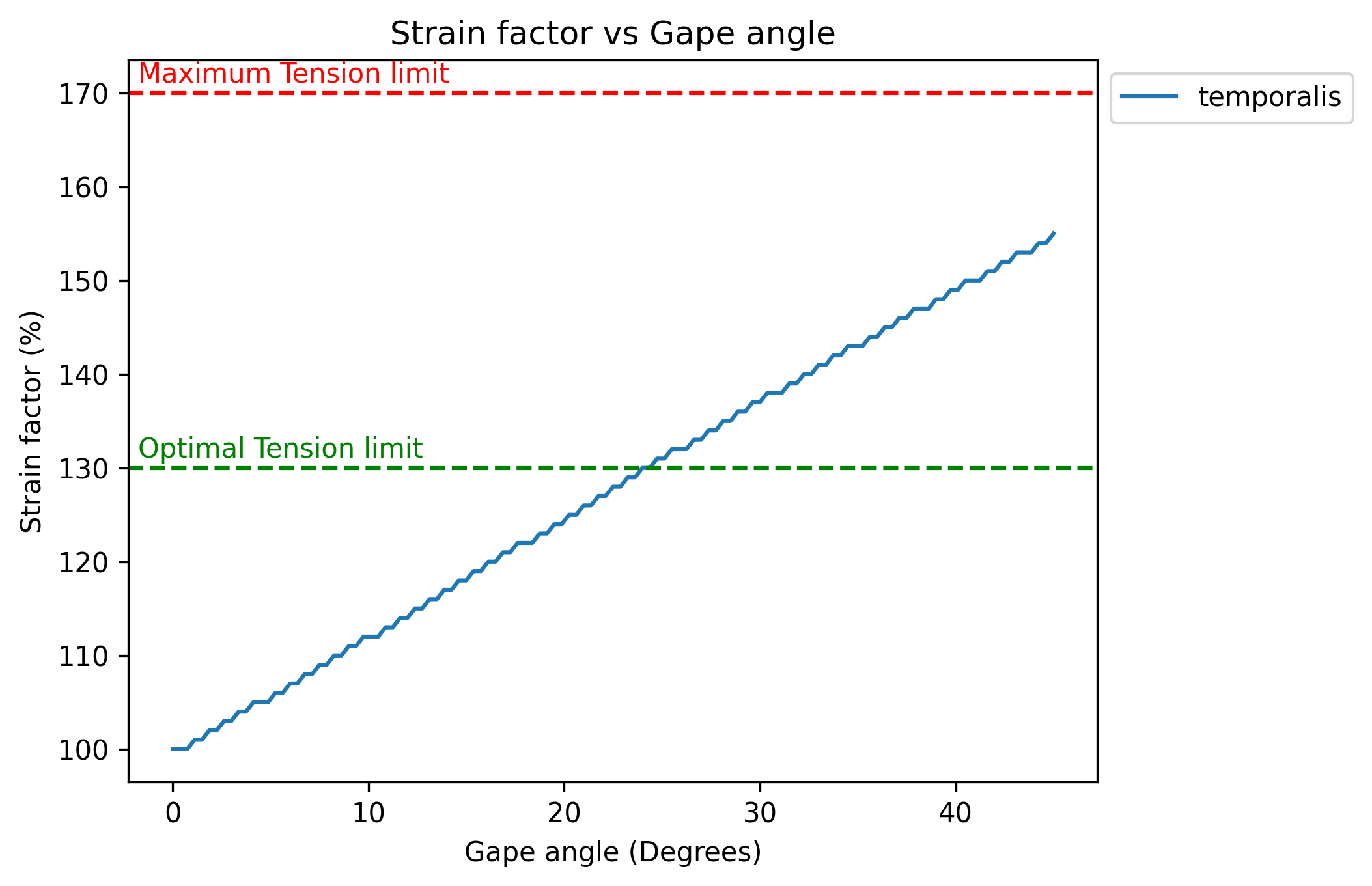
Additionally, an animated chart will be generated showing the length of the muscle fibers at each frame of the simulation. The generation of the simulation is a fast process and usually takes only a couple of seconds. Once finished, the user can play and stop the simulation by pressing the play and stop buttons in the timeline or by pressing the space bar. The user can also move the timeline to see the length of the muscle fibers at any frame of the simulation. The bars in the chart will be colored and will grow as the length of the muscle fibers increase. The bars will remain green if the length of the muscle fibers is less than the optimal length, and will turn red if the length of the muscle fibers is more than 170% of the optimal length (the failure point at which the muscle fibers will break).
8 Output results
An additional button named Render Simulation is available as last option. This button will generate a video of the simulation. The default resolution is 1920x1080 pixels and the default format is MPEG-4. The video will be saved in the selected folder with the name of the project. The video will show the animation of the simulation. The rendering process may take some time depending on the speed of your computer. The video use the first camera in the Scene to render the animation, for this reason is important to not delete the camera or keep the initial camera that Blender creates when you start a new project. Of course, you are free to use any other configuration for rendering the video using the Blender interface.
The CSV file will provide the following information:
The plots generated during the simulation may present the following format if the extension version or the add-on version is used:
References
Lautenschlager, Stephan. 2015. “Estimating Cranial Musculoskeletal Constraints in Theropod Dinosaurs.” Royal Society Open Science 2 (11). https://doi.org/10.1098/rsos.150495.